 |
Preparing Cast Iron Alloys |
|---|
 |
Preparing Cast Iron Alloys |
|---|
Metallography in Poland
Editor's Note: We are extremely pleased to be able to present to you in
this issue the superb work of Mrs. Janina Radzikowska, senior metallographer
at the Foundry Research lnstitute in Kraków, Poland. The very high
quality of her work should be an inspiration to metallographers everywhere.
Cast irons can exhibit a wide range of microstructural constituents depending upon their composition and heat treatment. Their preparation is difficult due to the need to properly retain the graphite phase when it is present. The presence of micro-shrinkage cavities also presents problems, particularly controlling bleedout of fluids and etchants. Metallographic examination may involve only qualitative assessments, for example, to define the type and relative size of the graphite phase and identify phases and other constituents such as nitrides and inclusions. There has been a trend in the foundry industry to become more quantitative with image analysis measurements of the amounts of phases, graphite shapes, and nodule density. In our research work, we quantify structures fully. However, most foundries do not need to be as rigorous in quality control studies.
Preparation Procedures
For our work, which often involves quantitative measurements using image
analysis, we must faithfully reveal the true structure. Thus, our preparation
procedure is more elaborate than that used by many foundries. We utilize
color tint-etching methods extensively, and these require a very high-quality
preparation practice.
For the work shown here, I used the following procedure with slight modifications depending upon whether or not the specimen was to be etched and if a tint etch was to be used. Mounted specimens were placed in a holder for six (usually) specimens. Central force and complementary rotation (platen and holder rotating in same direction) were used. The steps were:
1) 120 grit SiC paper, 300 rpm, 100N (22.5 Ibs.) force until all surfaces
are coplanar (water coolant)
2) 240 grit SIC paper, 300 rpm, 100N force for 2 minutes (water coolant)
3) 9µm METADI® Diamond Paste on an
ULTRA-PADTM Cloth, 150 rpm, 100N force for
3 minutes
4) 3µm METADI® Diamond Paste on a
TEXMET® 1000 pad, 150 rpm, 120N (27 Ibs) force, for 3 minutes
5) 1µm METADI® Diamond Paste on a
TEXMET® 1000 pad, 150 rpm, 100N force, for 2 minutes
6) Specimens etched lightly with 4% HNO, in alcohol (nital)
7) MASTERPREPTM Alumina Polishing Suspension
used on a MICROCLOTH® Polishing Cloth wet with water, 150
rpm, 90-120N (20-27 Ibs) force (depending on degree of etch), for 1.5-2 minutes
(depending on degree of etch)
(WebMasters' Note: For those unfamiliar with Buehler products; ULTRA-PADTM is a hard woven polyester cloth, TEXMET® 1000 is a napless nonwoven chemotextile polishing pad, MICROCLOTH® is a medium nap synthetic rayon cloth, and MASTERPREPTM is a finely dispersed non-agglomerated .05 micron Alumina suspension.)
METADI® Fluid was used as the lubricant/extender with the diamond abrasives. After each polishing step (Nos. 3, 4, 5 and 7), the specimens were washed with alcohol and blown dry with compressed air (which must be clean and dry). Washing with water sometimes results in corrosion stains on the surface, so I usually use only alcohol for the final cleaning step (No. 7). lndividual force can also be used, especially if I do not have enough specimens to fill the holder (divide the force values given above by 6 to determine the individual force to use).
Microstructures
One should always begin microstructural investigations by examining the
as-polished specimen before etching. This is a necessity, of course, for
cast iron specimens if we are to properly examine the graphite phase. Brightfield
vertical illumination will be our starting point, but the benefits of crossed
polarized light will also be explored.
Cast irons with a composition equivalent to about 4.3% C solidify as a eutectic. Because cast irons are not simple binary Fe-C alloys, it is usual practice to calculate the carbon equivalent (CE) value which is the total carbon content plus one-third the sum of the silicon and phosphorus contents. If the CE is > 4.3, it is hypereutectic; if it is < 4.3, it is hypoeutectic. Table 1 lists the CE values and compositions for each cast iron shown in this issue.
In the Fe-C system, the carbon may exist as either cementite, Fe,C, or as graphite. So the eutectic reaction is either liquid transforming to austenite and cementite at about 1130°C or liquid transforming to austenite and graphite at about 1135°C. Addition of elements such as silicon promote graphite formation. Slow cooling rates promote graphite formation, while higher rates promote cementite. The eutectic grows in a cellular manner with the cell size varying with cooling rate which influences mechanical properties.
|
Gray lron Figure 1 shows interdendritic flake graphite in a hypoeutectic alloy (see Table 1 for composition of alloys) where proeutectic austenite forms before the eutectic reaction. This type of graphite has been given many names. In the US it is referred to as Type D (ASTM A247) or as undercooled graphite. It was thought that the fine size of the graphite might be useful, but it is not technically useful as it always freezes last into a weak interdendritic network. Figure 2 shows more regularly-shaped graphite flakes in an alloy (Table 1) of higher carbon content, although still hypoeutectic. While flake lengths in Figure 1 are roughly 15-30µm, flake lengths in Figure 2 are in the 60-120µm range. Figure 3 shows somewhat coarser flakes (250-500µm length range) in a higher carbon content cast iron (Table 1). Other graphite forms are also observed. For example, Figure 4 shows disheveled graphite flakes in a casting. Note that a few nodules are present. This appears to be a mix of B- and D-type flakes. Figure 5 shows a hypereutectic gray iron where very coarse flakes form before the eutectic which is very fine. This is similar to C-type graphite.
Nodular Iron Nodule size and shape perfection can vary depending upon composition and cooling rate. Figure 6 shows fine nodules, about 15-30µm in diameter, while Figure 7 shows coarser nodules (about 30-60µm diameter) in two ductile iron casts (see Table 1 for compositions). Note that the number of nodules per unit area is much different, about 350 per mm2 vs.125 per mm2, respectively.
Compacted Graphite |
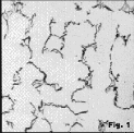 Figure 1 |
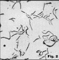 Figure 2 |
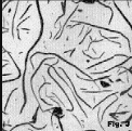 Figure 3 |
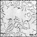 Figure 4 |
|
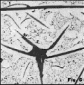 Figure 5 |
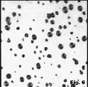 Figure 6 |
|
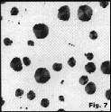 Figure 7 |
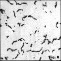 Figure 8 |
| Go to: | [FAQ] | [Home] |